LogicCircuit – is free, open source educational software for designing and simulating digital logic circuits. Intuitive graphical user interface, allows you to create unrestricted circuit hierarchy with multi bit buses, debug circuits behavior with oscilloscope, and navigate running circuits hierarchy.
Creating sub circuits with LogicCircuit
In order to build more advanced circuits you need to create reusable logical circuits.
To create it click menu Circuit/New Logical Circuit.
To switch between your circuits you can double click them on the left panel or pressing Ctrl + Tab or Ctrl + Shift + Tab to navigate through circuits in reverse historical order. Press Tab more than once while holding Ctrl to navigate further in the history.
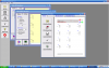
After you've created a new logical circuit you want to rename it and change text on its symbol.
To change properties of current logical circuit double click anywhere on the design surface, but not on any symbol. The circuit properties dialog will pop up. You also can open the same dialog by clicking menu Circuit/Logical Circuit.
Input and output pins of LogicCircuit
After you've created a new circuit it does not have any pins on its symbol's edges.
In order to wire it to other circuits you should define its input and output pins. This is very simple; just drag and drop as many input and output pins on the design surface of your circuit.
By default all input pins goes to the left side of the circuit symbol and output ones to the right side.
To change properties of the pin just double click it on the design surface and pin dialog will pop up.
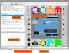
When you first open LogicCircuit it will be one empty logical circuit visible on the right pane of the program window named "Main".
To create you first circuit just drag and drop any item (for example a button) from the left pane to the design surface.
To wire your circuits connect output pin of one circuit with one or more input pins of another one. All pins are bold black dots on the edges of circuit symbols. All you need to do is just draw wires with your mouse.
You can select and move multiple symbols on your circuit.
Hold Ctrl key on your keyboard and click items on the design surface to select or unselect them.
Click wire while holding Shift key to select entire "conductor".
There are bunch of selection commands in the Edit menu.
When you moving symbols over the diagram wires connected to them will be sticking to the pins. If you want to move the symbols without wires hold Shift while dropping at the desired location.
You can also pan the entire surface in all 4 directions by holding Ctrl key and dragging any free space of the diagram. If you scroll your mouse wheel it will scroll the diagram vertically. Holding the Ctrl key and spinning the wheel will scroll the diagram horizontally. Finally, if you hold the Ctrl key and spin the wheel you can zoom the diagram in and out.
To edit properties of the symbol on the design surface double click it and the property dialog will pop up. However double clicking symbol of logical circuit will open it on the design surface.
Now you have your first circuit ready and can try to power it up and see how it works, with LogicCircuit.